

1. Integrated Components & Features
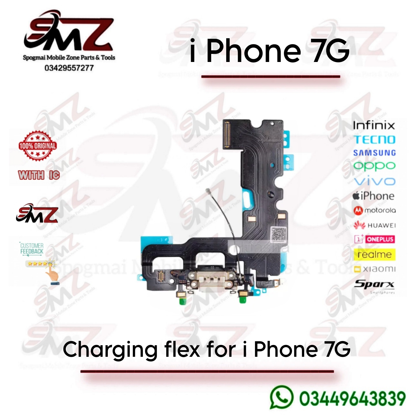
The charging flex ribbon combines several critical components into a single piece:
- Lightning Port Connector: Used for power delivery, syncing data with iTunes, and connecting Lightning headphones.
- Dual Bottom Microphones: Embedded on the lower flaps of the flex to capture your voice during standard cellular calls, voice memos, and loudspeaker calls.
- Antenna Contacts: Relays cellular and network signals from the main logic board down to the bottom speaker enclosure.
- Taptic Engine & Loudspeaker Connections: Features specific gold-plated pressure pads where the bottom speaker and Taptic Engine make electrical contact once screwed down.
2. Technical Specifications
- Device Compatibility: iPhone 4.7-inch screen models (A1660, A1778, A1779). Note: It will not fit the 5.5-inch iPhone 7 Plus.
- Material: High-grade, flexible printed circuit board (FPC) layered with microscopic copper traces.
- Color Matching: The visible plastic rim around the Lightning port opening is matched to the outer color of your iPhone (e.g., Black/Space Gray for dark phones, White/Silver/Gold/Rose Gold for lighter variants).
3. Common Symptoms of Failure
If this flex ribbon is torn or malfunctioning, you will experience one or more of the following issues:
- The phone refuses to charge or only charges when the cable is held at a specific angle.
- Computers fail to recognize the device when plugged in.
- People cannot hear you during normal phone calls, or your audio sounds heavily muffled (failing microphone).
- Weak or dropping cellular signals.
4. Installation & Repair Overview
Replacing the charging flex requires a moderate-to-high difficulty teardown. Because it sits flat against the bottom chassis of the aluminum housing, several layers of parts must be extracted first:
- Opening: Remove the two bottom Pentalobe screws and open the screen carefully toward the right side like a book.
- Disconnection: Disconnect the battery terminal first to eliminate the risk of short-circuiting internal chips.
- Component Removal: Remove the loudspeaker enclosure, the Taptic Engine, and unclip the lower cellular antenna wires.
- Board Loosening: The upper segment of the flex sits tucked underneath the main logic board. You must slightly unscrew and lift the logic board to pull out the old port safely.
- Adhesive Release: The flex is held tightly against the chassis by strong factory adhesive. A few drops of Isopropyl alcohol (99%) make it significantly easier to pry out without bending the frame.

Reviews
There are no reviews yet.